Quick answer
For a common 120/240V portable-generator system, the generator may use an L14-30R receptacle, the cord may use an L14-30P at the source and L14-30R at the destination, and the building inlet may be marked L14-30P. A 125V L5-30 system is different. Confirm every label and have the inlet and transfer equipment installed as one system.
Identify the complete 30A system before choosing the box
A common portable-generator home-backup path uses the L14-30 family, rated 30A at 125/250V with a four-wire grounding configuration. The generator usually presents an L14-30R receptacle, while the exterior inlet presents male contacts behind a weather cover because it receives the cord connector.
Some 30A generators provide only 125V through an L5-30 or TT-30 receptacle. Those sources do not become 125/250V when connected to a four-contact inlet. The generator manual and receptacle label must control the inlet and transfer design.
An inlet receives power; an outlet supplies power
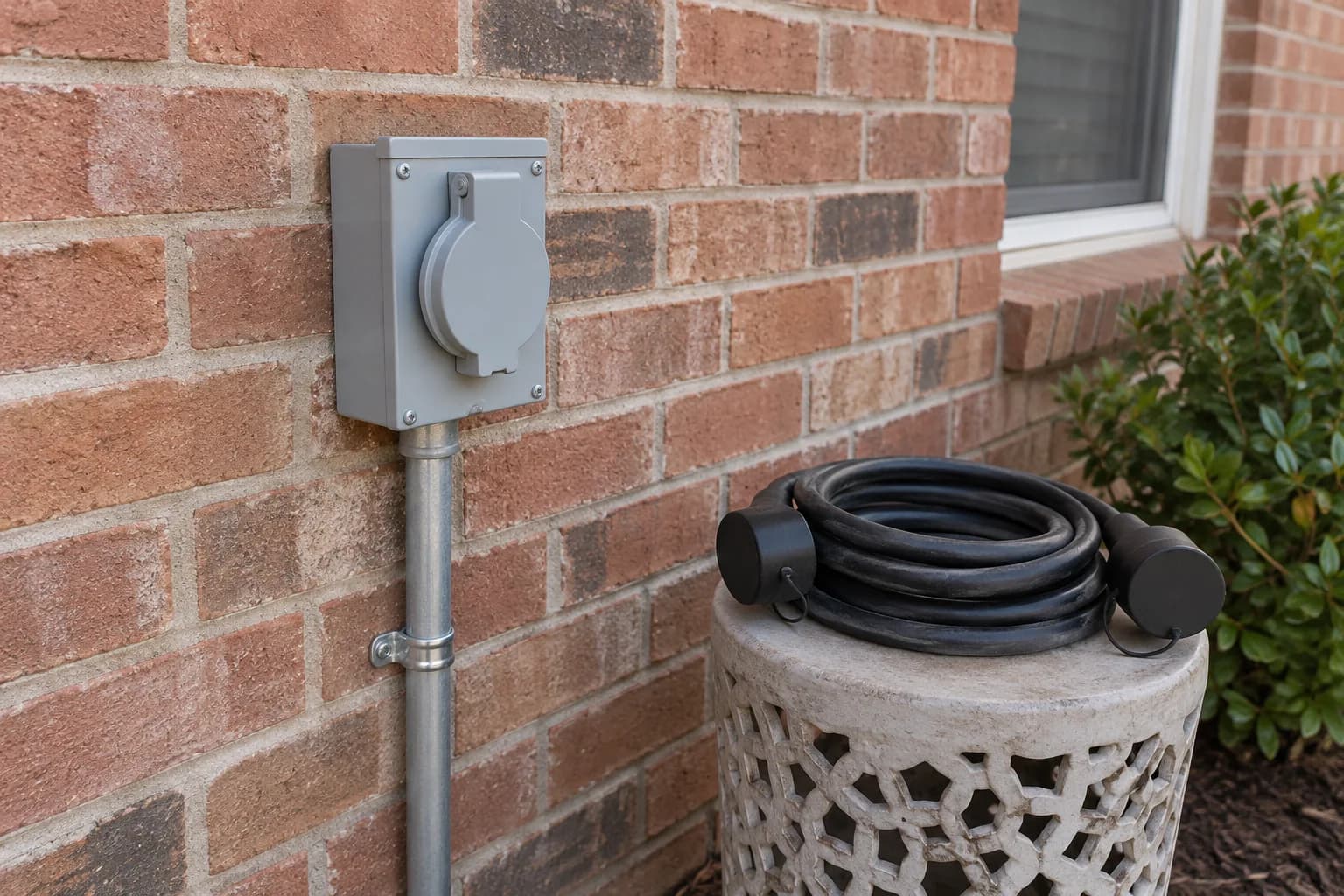
The direction of power matters. A building power inlet is designed to receive generator power from a cord and route it to transfer equipment. It is not a household outlet, dryer receptacle, or range receptacle. The inlet cover, enclosure, terminals, conductor space, and environmental rating must suit the installation.
The generator end and inlet end of the cord may use devices from the same L14-30 family, but the plug and connector suffixes differ. Confirm the cord assembly description instead of assuming that any four-prong 30A cable has the correct orientation.
| Position | Typical marked device | What to verify |
|---|---|---|
| Generator receptacle | L14-30R | 125/250V output and breaker rating |
| Cord source end | L14-30P | Mates with the generator receptacle |
| Cord inlet end | L14-30R | Mates with the building inlet |
| Building power inlet | L14-30P | Weather rating and transfer-system compatibility |
| Transfer equipment | Model-specific | Source isolation, circuits, neutral and service ratings |
Product to compare
Amazon · paid linksWEN PC3025 — 25 ft L14-30 generator cord
Compare this cord after confirming an L14-30R generator outlet and a matching L14-30P destination. Read both endpoint labels before choosing a cable.
For this connection: Only compare this L14-30 cord after confirming an L14-30R source and an L14-30P inlet. The cord does not provide source isolation; the building still needs approved transfer equipment and a qualified installation review.
- L14-30P → L14-30R
- 25 ft
- 10/4 SJTW
- 30A · manufacturer 250V rating
Amazon product code (ASIN): B0C86KSLYX
See the current price and available sellers on Amazon.
Advantages
- Locking L14-30 connections at both ends.
- Four-conductor 10/4 cable for this connector family.
- SJTW jacket specified for outdoor use.
Limitations
- A 25 ft length may not cover your cable route.
- Does not fit TT-30 or L5-30 equipment.
- A building connection still needs the correct inlet and transfer equipment.
Check before buying: Does not fit TT-30 or L5-30 equipment. Building connections also require the correct inlet, transfer equipment, and a site-specific electrical review.
Based on manufacturer specifications; not independently field-tested by CordFind. Confirm the model and both connector labels before buying.
The inlet does not replace a transfer switch or interlock system
An inlet only provides a listed connection point. Approved transfer equipment is still required to prevent generator power and utility power from being connected incorrectly. Depending on the design, the system may use a selected-circuit transfer switch or other approved equipment suitable for the panel and service.
The qualified installer must coordinate source isolation, breaker compatibility, conductor ratings, grounding and bonding, neutral treatment, circuit selection, labels, and operating instructions. A larger inlet does not correct a generator that cannot support the selected loads.
Place the inlet around the safe generator location
The inlet location should support the manufacturer-required outdoor generator position without routing a cord through a window, door, or area where it can be crushed. Portable generators must remain outside and far from doors, windows, vents, and occupied spaces, with exhaust directed away from buildings.
The enclosure must be approved for its environment and installed in the permitted orientation. The cord should reach without being stretched, coiled under heavy load, submerged, exposed to exhaust heat, or placed where vehicles and foot traffic can damage it.
Commission the inlet, cord, transfer equipment, and load plan together
After installation, the electrician should verify device ratings, conductor terminations, source isolation, labels, transfer operation, selected circuits, and the documented generator connection. The homeowner should receive a written operating sequence that begins with the generator outside and unloaded.
Test the system with the planned loads before an outage. Record which circuits are served, which loads must be scheduled, and which motor starts cannot overlap. Recheck the cord and inlet before each use for damage, moisture, loose parts, or heat discoloration.
Frequently asked questions
Common questions
What plug is used for a 30 amp generator inlet box?
A common 120/240V system uses an L14-30P inlet, but 125V L5-30 systems also exist. Confirm the generator output and transfer design rather than selecting by amperage alone.
Can a 30 amp inlet power an entire house?
The inlet is limited by the 30A source and complete system. Whether selected loads can run depends on their running and starting demand, the generator rating, and the transfer design.
Can I install a generator inlet without a transfer switch?
The inlet alone does not isolate generator power from utility power. Building wiring needs approved transfer equipment installed for the specific electrical system.
How long should the generator inlet cord be?
Use enough length to meet the generator manufacturer’s outdoor placement requirements without crushing, heating, or exposing the cord to damage. Then verify voltage drop for the actual load.
Primary references
CordFind summarizes connector specifications and public safety guidance. Always follow the instructions supplied with your equipment.
- Honda: Transfer Switch Recommendations
- Honda: Generator Receptacle Selection
- Leviton: L14-30R Product Specifications
- OSHA: Grounding Requirements for Portable Generators
- CPSC: Male-to-Male Extension Cord Warning