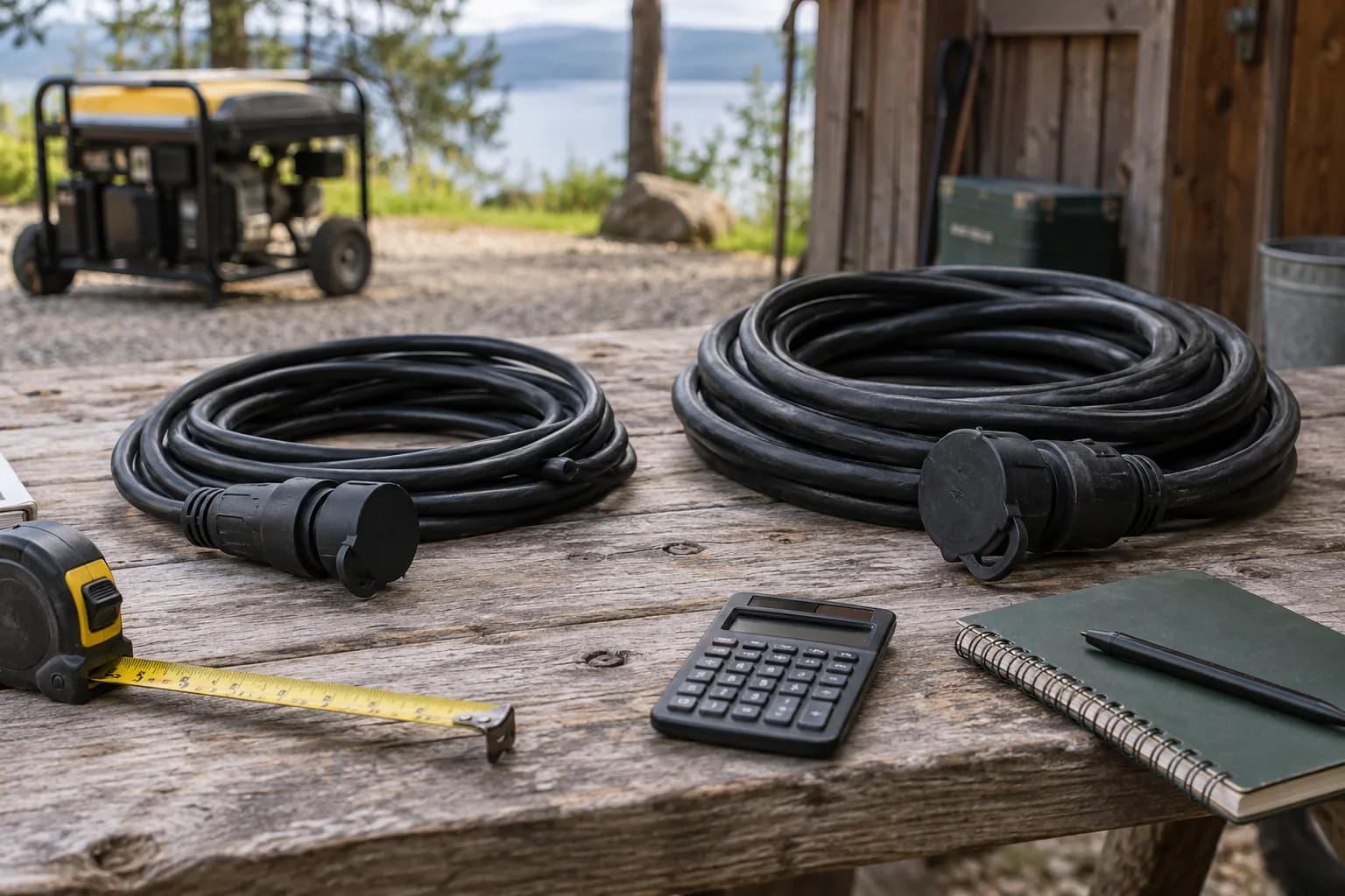
Quick answer
Choose 15, 20, 30 or 50A, select 120 or 240V, and enter a one-way length from 10 to 200 feet. The calculator estimates voltage drop at that current and identifies the smallest listed copper gauge that passes both planning checks. Separately verify the complete cord assembly, compatible connectors and equipment instructions; a gauge result does not approve a connection.
Interactive gauge check
Check conductor size and voltage drop
| Gauge | Planning ampacity | Drop at 50 ft | Status |
|---|---|---|---|
| 14 AWG | 15 A | 3.2% · 7.6 V | Ampacity |
| 12 AWG | 20 A | 2.0% · 4.8 V | Ampacity |
| 10 AWG | 30 A | 1.2% · 3.0 V | ✓ Passes |
| 8 AWG | 40 A | 0.8% · 1.9 V | ✓ Passes |
| 6 AWG | 55 A | 0.5% · 1.2 V | ✓ Passes |
| 4 AWG | 70 A | 0.3% · 0.7 V | ✓ Passes |
Smallest listed planning size
10 AWG copper1.2% drop · 237.0 V at the loadPlanning estimate for copper conductors at the stated one-way length. Flexible-cord ampacity depends on the complete listed assembly, jacket, temperature rating, conductor count, and application. Verify the actual product and manufacturer instructions.
Check your connector endpoints separately with Cord Finder, then verify the complete cord assembly rating.
Enter current and one-way distance
Use the current you want to check, with the circuit voltage and the actual cord route. The tool offers four current values; it does not measure your load or infer current from a generator’s maximum watts. The length control is the one-way distance between generator and load, not the combined length of outgoing and returning conductors.
The estimate uses a two-conductor circuit path: voltage lost = 2 × current × one-way feet × copper resistance per foot. Percentage drop is voltage lost divided by the selected supply voltage. It does not model a shared neutral, unbalanced split-phase loads, three-phase wiring or generator regulation.
Read both checks in each gauge row
A row passes only when its stated planning ampacity covers the selected current and its estimated voltage drop is within the selected 3% or 5% limit. A row can fail one check while passing the other. Lower AWG numbers identify larger conductors.
The highlighted gauge is the smallest size in this limited table that meets those two assumptions. It is a size to investigate, not a universal flexible-cord rating. A listed generator extension cord or generator cord assembly can have a different permitted current because of its jacket, conductor count, temperature, terminals and intended use.
Compare 25, 50 and 100 feet at the same load
These are calculated examples, not measurements of a purchased cord. Each row uses 30A, a 3% drop limit and the same resistance constants as the tool above. Notice that doubling the run can change the smallest passing gauge, while changing supply voltage changes the percentage drop.
Do not move the generator closer to an occupied space to make a smaller cord pass. Preserve safe outdoor placement and choose an appropriate rated assembly for the required route.
| Supply | One-way length | Smallest passing listed gauge | Calculated voltage lost | Calculated drop |
|---|---|---|---|---|
| 120V | 25 ft | 10 AWG | 1.50V | 1.25% |
| 120V | 50 ft | 10 AWG | 3.00V | 2.50% |
| 120V | 100 ft | 6 AWG | 2.37V | 1.98% |
| 240V | 100 ft | 10 AWG | 5.99V | 2.50% |
Compare 10 and 12 AWG at 100 and 200 feet
For a 120V, 20A two-conductor path, the calculator’s fixed copper assumptions give the results below. These are steady-state calculations using one-way cord length, not measurements or approvals of a flexible-cord product. At 100 feet, 10 AWG has less drop than 12 AWG, but neither meets the tool’s 3% target. Only 10 AWG meets a 5% comparison target. At 200 feet, neither meets either target.
Amp rating and voltage drop are separate checks. Even if a particular 12 AWG assembly is manufacturer-rated for the intended 20A load and environment, that rating does not erase its calculated 6.35V loss over this 100-foot example. Likewise, choosing a heavier gauge does not increase the ratings of its plug, connector or generator receptacle. Review the actual assembly, starting current and equipment input limits before choosing a long run.
| One-way run | Gauge | Voltage lost | Drop | 3% / 5% comparison |
|---|---|---|---|---|
| 100 ft | 12 AWG | 6.35V | 5.29% | Fails / fails |
| 100 ft | 10 AWG | 4.00V | 3.33% | Fails / meets |
| 200 ft | 12 AWG | 12.70V | 10.59% | Fails / fails |
| 200 ft | 10 AWG | 7.99V | 6.66% | Fails / fails |
The values behind the estimate
The tool uses fixed copper resistance values and simplified planning ampacities shown here. It makes no adjustment for conductor temperature, plug contact resistance, generator voltage sag, cable reactance or starting transients. The 3% and 5% controls are comparison targets; neither is a universal approval threshold for every device or installation.
For a motor or compressor, the current during starting may be much higher than the selected operating current. Check the equipment’s starting needs separately. A steady-state calculation cannot demonstrate that a long cord will start a particular pump or air conditioner.
| Copper gauge | Resistance (ohms per 1,000 ft) | Tool planning ampacity |
|---|---|---|
| 14 AWG | 2.525 | 15A |
| 12 AWG | 1.588 | 20A |
| 10 AWG | 0.999 | 30A |
| 8 AWG | 0.6282 | 40A |
| 6 AWG | 0.3951 | 55A |
| 4 AWG | 0.2485 | 70A |
Check the endpoints after comparing gauges
Use Cord Finder for the separate connector-compatibility check. Record the designation at the generator and at the load or inlet, then verify voltage, conductors, grounding and the complete assembly rating. A thicker cable cannot correct an incompatible generator plug.
A building connection still requires suitable transfer equipment, an approved inlet and qualified installation. This calculator does not inspect panel wiring, neutral bonding, local requirements, damaged equipment or installation quality.
Frequently asked questions
Common questions
Can watts alone determine generator cord size?
No. Connector type, voltage, current, distance, conductor count, load behavior, and product ratings also matter.
Does the calculator check generator plugs?
No. It compares copper gauges and estimated voltage drop. Use Cord Finder for the separate connector-compatibility check, then verify the complete cord assembly.
What gauge does the tool show for a 100 foot, 30A cord?
With its fixed assumptions and a 3% target, it shows 6 AWG at 120V and 10 AWG at 240V. These are planning examples, not approval of a particular cord or split-phase installation.
Does the calculator replace an electrician?
No. It cannot inspect or approve building wiring, grounding, transfer equipment or site-specific conductor requirements.
Why does distance matter?
Longer conductors add resistance and voltage drop, which can affect equipment performance and heat.
Is 10 gauge better than 12 gauge for a 100 or 200 foot generator cord?
Its lower conductor resistance reduces calculated voltage drop at the same load and distance. That alone does not approve the cord. In the tool’s 120V, 20A examples, 10 AWG drops 3.33% at 100 feet and 6.66% at 200 feet; check the complete assembly rating and equipment requirements.
Primary references
CordFind summarizes connector specifications and public safety guidance. Always follow the instructions supplied with your equipment.
- OSHA — Using Portable Generators Safely
- OSHA — Use of Equipment, 1910.334