Quick answer
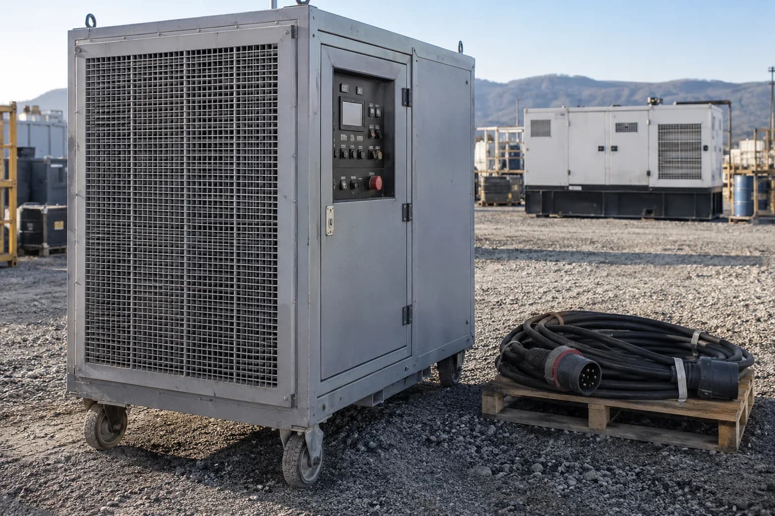
Use a qualified test plan based on the generator rating, fuel, duty, manufacturer instructions, facility requirements, connected system, and reason for testing. Define load type, steps, duration, acceptance limits, instrumentation, connection method, outage contingency, and stop conditions before the test. Record voltage, current, frequency, power, power factor, temperatures, pressures where supported, alarms, emissions observations, and recovery. Do not improvise a load bank from space heaters or connect temporary high-current conductors without engineered equipment and qualified personnel.
Match the test to a specific question
Commissioning, maintenance, troubleshooting, low-load concerns, repaired equipment, capacity verification, and regulated emergency systems can require different tests. Write the question first. A generic run at an arbitrary percentage may produce data without answering whether the generator meets its design requirement.
Confirm the applicable manufacturer procedure, engineer-of-record criteria, facility standard, contract, insurer requirement, and authority. Residential standby, rental, industrial prime-power, data-center, and healthcare systems should not share one undocumented test template.
Choose the load type that represents the intended evidence
A resistive bank primarily applies real power at a power factor near one. Reactive elements allow testing of kVA and power-factor behavior. Actual electronic, motor, rectifier, and constant-power loads can respond differently from a constant-impedance bank. Caterpillar notes that load-bank acceptance may not represent every constant-power load response.
Define whether the test uses steady steps, sudden block loads, gradual loading, transfer under building load, or a combination. The generator rating, alternator, engine, controls, and load-bank capacity must support the procedure.
Plan isolation, connection and outage contingency
Document the single-line path, breakers, conductor ratings, temporary connection point, phase rotation, grounding and bonding, neutral, clearances, barriers, cable protection, ventilation, exhaust, fuel, and fire response. Determine what happens if utility power fails while the generator is committed to the bank.
Dedicated docking or load-bank connection equipment can reduce unsafe temporary work and improve restoration planning. Temporary high-current connections expose severe shock, arc-flash, mechanical, and fire hazards and belong to qualified personnel using an approved procedure.
Record performance at every step and transition
Record generator hours, ambient conditions, selected fuel, pretest inspection, oil and coolant status where applicable, battery, voltage by phase, current by phase, frequency, kW, kVA, power factor, load step, recovery, temperatures, pressures where supported, exhaust condition, leaks, vibration, controls, alarms, and protective-device operation.
Acceptance limits must come from the applicable design and manufacturer data. A stable final voltage does not erase an unacceptable transient, slow recovery, phase imbalance, overheating, fuel-pressure collapse, or protection failure. Stop conditions should be written before loading begins.
Ask for a report that another technician can interpret
Before the visit, ask the test provider to identify the equipment, procedure revision and acceptance criteria on the report. Each load point needs a timestamp and units. A note saying passed at full load is difficult to assess when it omits the selected fuel, applicable rating, load-bank type or duration.
Keep the planned load, measured response and final disposition in separate fields. A missing measurement is unresolved evidence, not a zero or a pass. The technician should identify any restriction on the test and which parts of the outage sequence were outside its scope.
| Record group | Information to retain | Question it answers |
|---|---|---|
| Equipment and basis | Generator and bank IDs; fuel; kW/kVA rating and duty; ambient conditions; hours | Which machine and operating limits were tested? |
| Procedure and instruments | Approved steps and duration; stop limits; instrument IDs and calibration status | Can the readings be traced to the agreed test? |
| Each load point | Timestamp; measured kW, kVA and power factor; phase voltages and currents; frequency | What load was actually applied? |
| Each transition | Load added or removed; voltage/frequency dip or rise; recovery time; alarms | Did the transient meet the documented criterion? |
| Closeout | Cooling and fuel observations; deviations; corrective actions; retest status; restored control mode | What remains open before the system returns to service? |
Read kW and kVA as different pieces of evidence
Consider an illustrative generator rated 100 kW and 125 kVA at 0.8 power factor on the selected fuel. A 60 kW resistive-bank reading at unity power factor is also 60 kVA: 60% of the stated kW rating, but 48% of the stated kVA rating. It demonstrates a different operating point from 60 kW at 0.8 power factor, which is 75 kVA.
The figures below are invented to explain a report, not CordFind measurements, acceptance limits or a loading schedule. The qualified provider still chooses the test points and decides whether the observed performance meets the project requirements. Neither row proves motor starting, UPS compatibility or transfer operation.
| Example recorded point | Power factor | Calculated kVA | Rating comparison |
|---|---|---|---|
| 60 kW with a resistive bank | 1.0 | 60 ÷ 1.0 = 60 kVA | 60% of kW; 48% of kVA |
| 60 kW with a suitable combined resistive/reactive bank | 0.8 | 60 ÷ 0.8 = 75 kVA | 60% of kW; 60% of kVA |
| Voltage, frequency and recovery | Record separately | Not established by kW ÷ PF | Compare measured response with the approved criteria |
Finish with a system record and corrective actions
A bank test can verify the generator package under its test load while leaving transfer switches, load management, motor starts, UPS interaction, selective coordination, branch circuits, and real operational sequences untested. Pair it with other functional tests when the system objective requires them.
Issue a report with equipment IDs, instruments and calibration status, diagram, procedure, raw readings, charts where available, alarms, photos, deviations, corrective actions, and retest status. Update maintenance hours and restore the system to its correct automatic or ready mode only after closeout.
Frequently asked questions
Common questions
What does a generator load bank test prove?
It shows how the generator performs under the defined bank load and procedure. It does not automatically prove every transfer, motor, electronic load, branch circuit, or real outage sequence.
How often should a generator be load-bank tested?
Use the exact manufacturer, facility, contract, engineering, insurer, and applicable standard requirements. There is no universal interval for every generator.
Is a resistive load bank enough?
It may answer real-power and thermal questions, but it may not represent reactive, motor, nonlinear, or constant-power loads. Match the bank and procedure to the intended evidence.
Can I use heaters as a homemade load bank?
Do not improvise a high-current test setup. Connection ratings, conductor protection, load control, ventilation, grounding, and fault energy require approved equipment and qualified work.
Primary references
CordFind summarizes connector specifications and public safety guidance. Always follow the instructions supplied with your equipment.
- Caterpillar: Constant Power Loads
- Caterpillar: Generator Underloading
- Caterpillar: Docking Station and Load Bank Considerations
- Caterpillar: Electrical Systems Commissioning