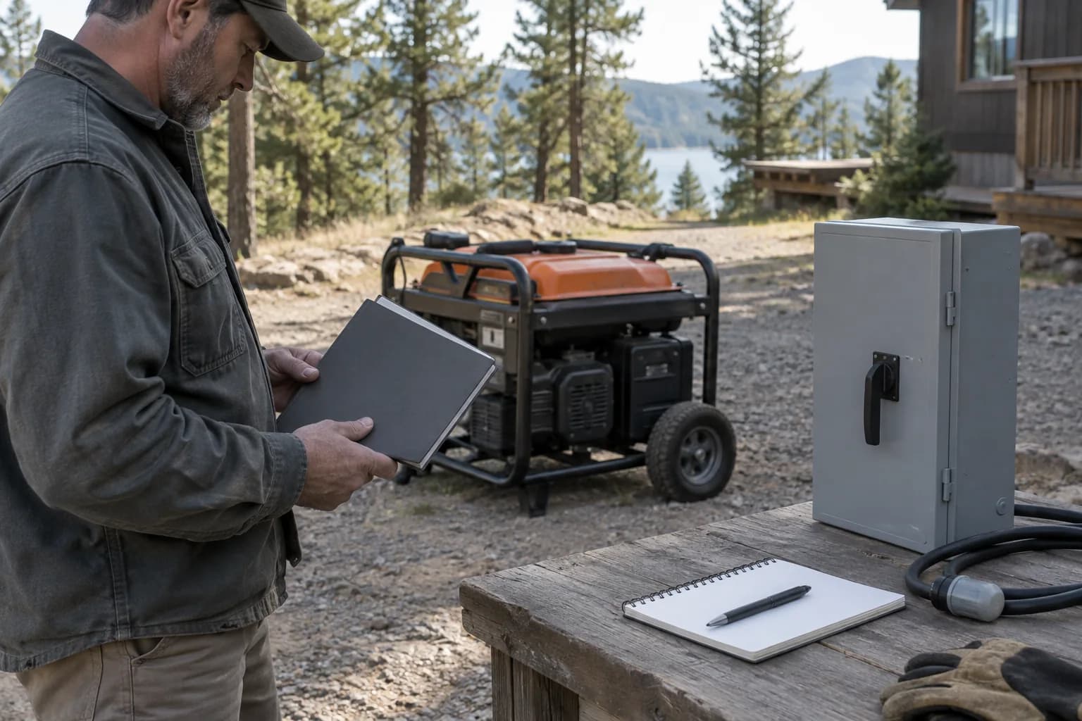
Quick answer
Do not change a neutral bond from a generic diagram. Identify the exact generator configuration, confirm it with the manual and appropriate testing, then match it to the approved transfer system. A system that switches the neutral can create a separately derived source with different bonding requirements from a system that leaves the service neutral connected. The generator, transfer equipment, grounding electrode system, GFCI protection, and building wiring must be reviewed together by qualified personnel.
Separate neutral bonding from grounding electrodes
A neutral-to-frame bond intentionally connects the grounded circuit conductor to the generator frame at a defined point. A floating-neutral generator does not make that connection at the generator. The equipment grounding conductors, receptacle grounding contacts, frame bonding, and any grounding electrode are related but distinct parts of the fault-current path.
Driving a ground rod does not automatically correct an incorrect neutral arrangement. Protective devices need an effective fault path. Multiple unintended neutral bonds can place normal return current on metal paths, while a missing required bond can prevent predictable fault clearing.
Direct cord-connected loads are different from building wiring
OSHA explains conditions under which a portable generator frame can serve as the grounding electrode when it supplies only equipment mounted on the generator or cord-and-plug-connected equipment through generator receptacles, with the required frame and grounding-terminal bonds. That guidance does not make every portable configuration interchangeable.
Confirm the manual, receptacle protection, GFCI requirements, cord grounding conductor, equipment condition, and work environment. Jobsite rules and household use cases can differ. A three-light receptacle tester cannot establish the complete bonding and transfer design.
The transfer switch determines whether the source may be separately derived
A transfer device that switches the ungrounded conductors but leaves the building neutral connected creates a different system relationship from a transfer device that also switches the neutral. The selected generator neutral configuration must match that design and its listing and instructions.
Do not assume an interlock, manual transfer switch, automatic transfer switch, RV system, or temporary distribution panel handles the neutral in the same way. Record the number of switched poles, neutral path, grounding electrode connection, generator bond, and required labels from the exact documents.
Treat GFCI trips and objectionable current as diagnostic evidence
A GFCI trip during an attempted building connection can indicate a neutral and grounding relationship that the proposed system has not resolved. Bypassing a GFCI, lifting a grounding pin, or altering a bond to make the trip disappear removes evidence without proving safety.
Qualified testing may include continuity checks with the source isolated, verification of the manufacturer configuration, inspection of transfer poles, and current measurements on grounding paths. The safe response to uncertainty is to stop, document the exact components, and have the system reviewed.
A neutral bonding plug needs permission for the exact setup
A neutral bonding plug creates a neutral-to-ground connection at the compatible source receptacle. It is a system change, not an ordinary power adapter or a substitute for a ground rod. WEN notes that floating-neutral sources can produce misleading readings on incompatible testers; correcting a tester indication is not evidence that the resulting supply arrangement is approved.
Obtain the generator model, its documented bond, the connected equipment requirements and any transfer neutral diagram before considering an accessory. Reliance publishes transfer-panel instructions that distinguish separately derived and non-separately derived connections. Those installation-specific instructions demonstrate why an accessory suitable for one cord-connected setup cannot be carried into a house connection on assumption.
| Exact setup | Required evidence | Decision boundary |
|---|---|---|
| Documented floating-neutral source with direct cord loads | Generator and load instructions explicitly permit the proposed bond/accessory | Use only the specifically approved arrangement |
| Generator already bonded to its frame | Manufacturer bond diagram | Do not add a second bond to clear an indication |
| RV with a power-management device | Generator, RV and protective-device requirements | A ground error alone is not accessory approval |
| House transfer with an unswitched neutral | Installer-confirmed neutral and existing system bond path | No generic bonding plug; match the approved transfer design |
| Transfer system that switches the neutral | Exact poles, source-bond and electrode plan | Have the complete system specified and accepted |
| EVSE or other source-checking equipment | Written source allowance and protective requirements | Do not force acceptance by changing a bond |
Create a one-page neutral and grounding record
Record generator model and serial information, manual revision, neutral-to-frame configuration, receptacle and GFCI details, transfer equipment model and pole count, neutral path, grounding electrode connection, inlet and conductors, and the installer or inspector decision. Keep this record with the outage procedure.
Recheck the record after generator replacement, transfer-equipment changes, panel work, RV modifications, or temporary distribution changes. A replacement generator with the same wattage and outlet can have a different neutral configuration, so wattage compatibility does not establish bonding compatibility.
Frequently asked questions
Common questions
Is a bonded-neutral generator safer than a floating-neutral generator?
Not by category. Safety depends on the complete supply and transfer arrangement. The correct configuration is the one required by the exact approved system.
Can I remove the neutral bond to stop a GFCI from tripping?
Do not do that from generic advice. A trip can reveal an incompatible or incorrectly designed connection. Stop and have the generator, transfer poles, neutral, and grounding paths reviewed.
Does an interlock switch the neutral?
Typical breaker interlocks coordinate ungrounded source breakers and do not by themselves establish a switched-neutral system. Verify the exact listed equipment and complete neutral path.
Can a multimeter tell me whether the neutral is bonded?
Qualified continuity testing with the source isolated can help verify configuration, but the result must still be matched to manuals, transfer equipment, protective devices, and the installation design.
Should I use a generator neutral bonding plug?
Only when the exact generator and connected equipment permit that arrangement and it agrees with the complete transfer, neutral, grounding and protection design. Do not add a bond to an already bonded source, force an EVSE to accept power, or treat a tester or RV error as permission.
Primary references
CordFind summarizes connector specifications and public safety guidance. Always follow the instructions supplied with your equipment.
- OSHA: Grounding Requirements for Portable Generators
- OSHA: Portable Generator Neutral Bond Interpretation
- OSHA: Wiring Design and Protection
- CPSC: Generators and Engine-Driven Tools
- WEN: Generator FAQ, Floating Neutral and Tester Compatibility
- Reliance: Transfer Panel Instructions, Neutral-System Distinctions